Finally! Proven Steps to Convert Your Chevy Into a 4-speed
Finally! Proven Steps to Convert Your Chevy Into a 4-speed
[This article was first published in Late Great Chevys, March 2001, pp 10-13]
Editor s Note: I would like to thank Bill for this excellent technical article. It shows a tremendous amount of work and effort and is really appreciated. I am always looking for quality “how-to” articles for our publication. They do not have to be major articles like this one, but maybe a page with 3 or 4 photos. I know that we have a lot of talent out there. Why don’t some of you ace mechanics submit something for our great publication? Denny Williams
I recently converted my 1963 Impala SS from a Powerglide to a Muncie wide-ratio 4-speed. I’ll do my best to explain the process of what I've done and give instructions for you to do the same. I'll also point out some of the problems that I encountered during the swap. I’m hoping that this article will save others some of the headaches that are normally involved in a conversion such as this one. I did the entire project by myself, but it would have helped to have a good friend or two to assist with the swap.
I had always dreamed of having a ‘63 Impala with a V-8 and 4-speed. Throughout the years, I had several 1962’s and a ‘64 SS, but never a 1963. It had been over 20 years since I owned my last Impala, when a good friend finally talked me into searching for one. I scanned Hemmings Motor News for weeks and narrowed my search down to a few 62’s, 63’s, and 64’s that were within a couple hours drive from my home in Virginia.

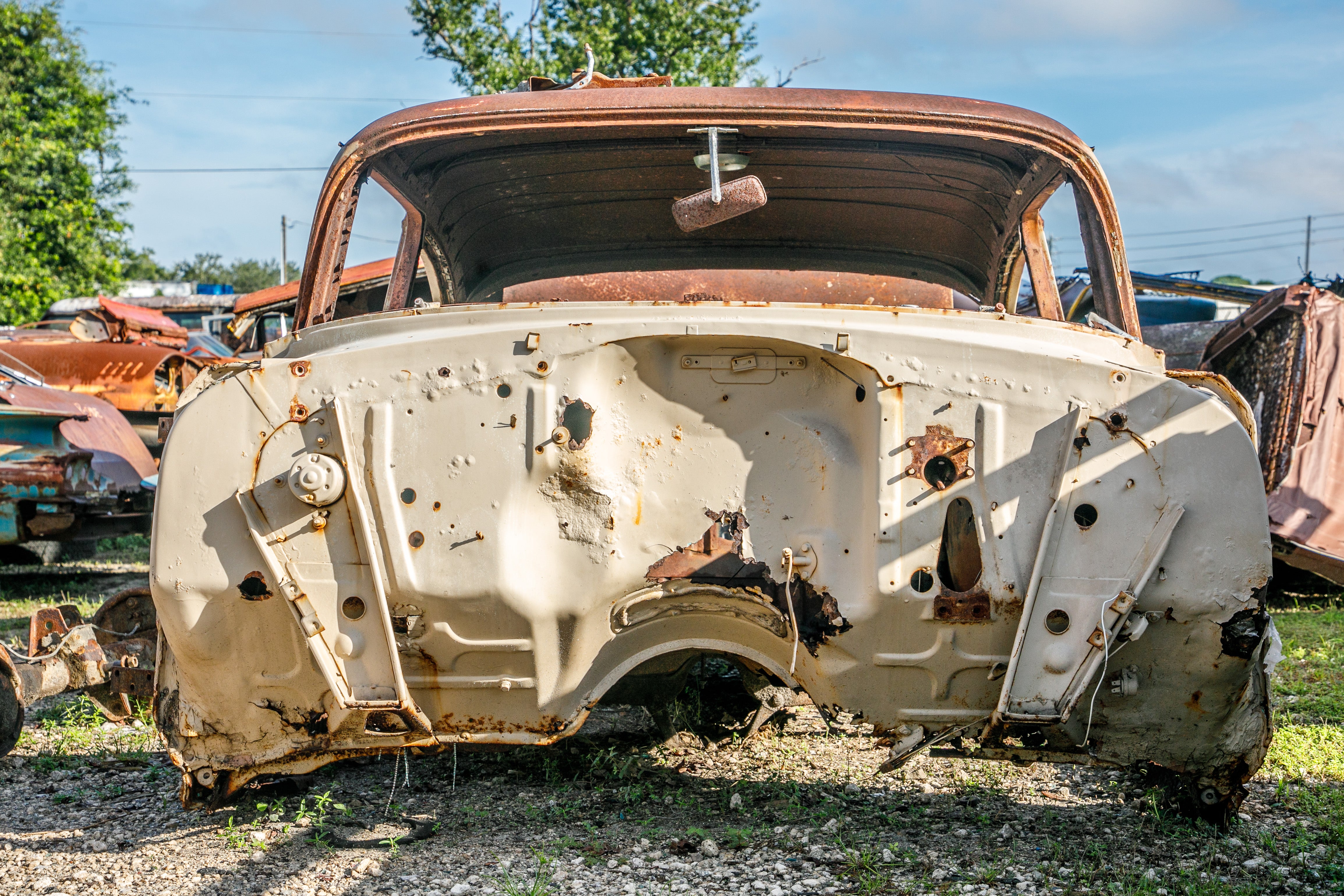
The second car I looked at was a gorgeous, black ‘63 Super Sport with red interior. It had the V-8 (283), but also had a Powerglide. I wanted a 4- speed!! Regardless, as soon as I saw this car, I knew I was going to buy it. I said to myself, “I can always convert it to a 4-speed later on.” I drove it for about a year and a half while I researched and collected parts necessary for the swap. Having an SS with a floor shift Powerglide (See photo #1.) was going to make the project much easier, since I wanted the end result to look as original as possible. I did not want a “chop job!” I was fortunate to find a mostly complete ‘63 Bel Air in a salvage yard. It had the 6-cylinder and 3-speed trans still intact. I pulled the bellhousing and flywheel from the donor car. I even took the clutch, pressure plate, and release bearing.

(See photo #2.) I only planned to use the clutch, pressure plate, and release bearing to match up to new ones. I also pulled the brake/clutch pedal assembly, the upper & lower clutch rods,the springs, and the Z-bar.

(See photo #3.) Not shown in the photo is the steering column floor seal, which I also removed from the donor car. (I could have easily just drilled a hole in my original PG floor seal where the upper clutch rod goes through the firewall.)
The left front fender and fender well were missing from the donor car, so I was able to chisel off the Z-bar bracket that is welded to the frame. (This was not easy work, and I only did it because I didn’t know replacement brackets were available.) I repainted the bellhousing and replaced the release fork boot. I had the flywheel turned, and bought a new 10 1/2-inch clutch assembly. (The original was 10-inches). I sandblasted and painted the clutch linkage and replaced the rubber brake and clutch pedal pads.

I searched unsuccessfully for a 4-speed or 3-speed w/OD drive shaft. (They are the same length.) I ended up picking up a worn out Powerglide drive shaft from a swap meet and completely disassembled it. (See photo #4.) Once the center carrier bearing and the transmission slip yoke were removed from the front shaft, I had it shortened from 26 13/16-inches to 24 5/8- inches, which is the length of a 4-speed forward shaft. I then sandblasted, painted, and reassembled the drive shaft with new universal joints and a new center carrier bearing assembly. I also replaced the original 16-spline slip yoke with a 27-spline, since I was going to use a Muncie transmission. (Note: 1959-1964 4-speed & 3-speed w/OD forward shafts are 24 5/8-inches, 1959-1964 3-speed & 1959-1961 Turboglide front shafts are 29 3/4- inches, and 1959-1964 Powerglide front shafts are 26 13/16-inches). Other necessary parts that were purchased for the swap are as follows

(See photo #5.): transmission tunnel seal, 1963 SS 4-speed shifter boot, transmission pilot bearing, release fork boot, transmission mount, firewall/steering column seal, Hurst Competition Plus Shifter, 1963 SS-style shifter handle to fit the Hurst shifter, and the 4-speed shift pattern plate for my 1963 console. (Not shown is the Z-bar ball stud that threads into the left side of the engine block.)

The 1963 Assembly Manual shows where to position the Z-bar bracket that is to be welded to the frame. With the left inner fender removed for easy access, a local welder had it done in a matter of minutes. I then threaded the Z-bar ball stud into the engine block. (See photo #6.)

I had to loosen the two clamps and slide the steering shaft coupling off the lower steering shaft to install the new firewall/steering column seal. (See photo #7.) I then installed the clutch/brake assembly and clutch linkage. (See photo #7.)

At this time, I put the front wheels up on ramps and raised the rear of the car until it was level. Place jack stands under the rear axle. Next, I removed the left front bucket seat and the center console. Fold the carpet over to expose the transmission tunnel plate. (See photo #8.)

Remove the shifter knob and the old shifter boot, and then remove the transmission tunnel plate to gain access to the shifter mounting bolts. (See photo #9.)

Remove the three bolts that attach the shifter to the transmission tailshaft. Disconnect the shifter linkage and remove the shifter. Also, disconnect the speedometer cable at this time. (See photo #10.)

The next step was to remove the drive shaft. Four nuts attach it to the differential. (See photo #11.)

Remove the two bolts that attach the center bearing assembly to the frame. Install a tailshaft plug or an old 16-spline yoke into the tailshaft of the transmission to keep it from leaking fluid. Photo #12 shows the old Powerglide drive shaft on the bottom, and the new, shorter, rebuilt, 4-speed drive shaft above.

Next, I removed the transmission cooling lines from the radiator and installed brass plugs in their place. (See photo #13.)

Remove the nuts from the transmission crossmember but leave the bolts in place for now. (See photo #14.)

Remove the sheet metal inspection plate that covers the torque converter. Remove the torque converter-to-flex plate bolts. (See photo #15.) You will need to rotate the engine to reach all four. Place a floor jack under the center of the transmission, and then remove the crossmember bolts.

Before lowering the jack, remove the distributor cap from the engine so it doesn’t get crushed against the firewall when the rear of the engine drops. Lower floor jack enough to reach the transmission cooling lines at the transmission. (Watch the distributor to firewall clearance). Remove the transmission cooling lines and install brass plugs in the transmission. (See photo #16.) Be sure that the transmission is centered on the floor jack. Lower the floor jack just enough to reach all of the bellhousing bolts.
At this point, I had to remove the backup light/neutral switch assembly and wiring from the left side of the transmission. If you have a column shift car, it will be in the column. On a 1964 SS, it’s in the console. I disconnected the wiring harness from under the dash and removed it. (I had to make an end around jumper wire for the neutral switch connector (purple wires) in the dash harness, so the car would start afterwards.) Remove the bellhousing bolts and very slowly pull transmission a few inches towards the rear of the car, while checking to make sure it is balanced on the floor jack. A few extra hands would be helpful here. Be sure transmission does not tip forward or the torque converter will fall out (very messy). Carefully lower the transmission all the way down. If you have the car up high enough, you will be able to slide the transmission out from under it. You may have to slide it off the floor jack first.

Remove the crossmember from the transmission. Photo #17 shows the rear of the engine with the transmission removed. Remove the six bolts that hold the flex plate to the crankshaft and remove the flex plate.

Photo #18 shows the rear of the engine with the flex plate removed and the pilot bearing installed. Notice the rear main seal leak !!!!
Note: I bought a pilot bearing for a Chevrolet with manual trans (only one listed, one size fits all). It didn't fit in the end of the crankshaft; the outside diameter of the bearing was too large. I called around and visited several parts stores and all had the same part, all too large. I suppose the crankshaft for Powerglide cars are different from crankshafts for standard shift cars. This became a real headache. With no other solution, I ground down the pilot bearing (equally, I hope) on a grinder until it fit in the end of the crankshaft. (I have since found that Year One, Inc. has a pilot bearing listed in their catalog that is for converting a Powerglide car to a manual trans.

Install flywheel front cover before installing the flywheel. Install the flywheel using new flywheel bolts. (See photo #19.) Grease pilot bearing and install clutch disk with alignment tool inserted into the pilot bearing.

(See photo #20.) Install the pressure plate and be sure that the clutch disk is aligned properly. Use new bolts on the pressure plate.

(See photo #21.) Install new release bearing and new release fork boot in the bellhousing and bolt the bellhousing into place.

(See photo #22.)
Note: The release bearing is another area that can cause headaches, since Chevrolet used several different length release bearings. The donor car came with a 1 7/8-inch release bearing. The new clutch I bought came with a shorter 1 7/32-inch release bearing. Twenty years ago, I installed a shorter (1 7/32-inch) release bearing in my ‘64 SS and it didn't work. Had to tear it all apart again and get a 1 7/8-inch bearing. Remembering that lesson from long ago, I traded the 1 7/32-inch bearing for a 1 7/8-inch. I put it in and it was too long !!!! Had to run out and buy a 1 7/32-inch release bearing, which by the way was the one the clutch assembly came with, and it fit perfectly. (I guess the lesson here is to use whatever release bearing comes with the clutch kit.) In this case, the pressure plate diaphragm springs extended further out to make up for the shorter release bearing.
Next is the transmission. I used a 1963 Muncie wide-ratio, but a Borg- Warner T-10 or a Saginaw would also fit. I will have more on transmissions and bellhousings later in the article. It’s a good idea to thread several long pilot bolts (with the heads sawed off) into the rear of the bellhousing. This will help align the transmission to the bellhousing. Install the shifter onto the transmission beforehand and adjust the shifter linkage, then just unbolt and remove the shifter handle. Bolt a new transmission mount (if necessary) to the tailshaft of the transmission. Remove the speedometer gear from the Powerglide and install it into the 4-speed. Place the transmission on the floor jack and try to balance it while raising the jack. (This is a real joy to do by yourself. Extra hands are VERY helpful here.)

Slide the transmission onto the pilot bolts in the bellhousing. If you aligned the clutch properly, it should slide right into place. You may need to put the transmission in gear and turn the output shaft to help mesh the input shaft splines with the clutch disk splines. With the floor jack still in place and hopefully some extra hands holding the transmission, remove the pilot bolts from the bellhousing and install the transmission bolts. You can now remove the floor jack if your distributor to firewall clearance is OK. (See photo #23). Install the shifter handle and speedometer cable before the rear of the transmission is raised back into place.
Place the floor jack under the transmission and raise up high enough to put the crossmember back into place. Bolt the transmission to the crossmember and bolt the crossmember to the frame. (Refer to photo #14 again.) Note: There are two sets of holes in the frame for the crossmember bolts. The lower set of holes are for Powerglide and 4-speed transmissions, the upper set of holes are for 3-speed transmissions.

Install the driveshaft. Use a 9/16-inch wrench on the center bearing bolts and a 1/2-inch wrench on the rear U-joint nuts. Photo# 24 shows the rear of the transmission with the shifter, speedometer cable, crossmember, and driveshaft installed.
Fill the transmission with 90- or 140-weight gear oil, using the filler hole in the side of the transmission. (See photo # 23.) Fortunately for me, the 1963 Impala SS used the same center console for both Powerglides and 4-speeds. Only the shift pattern plate is different.

Photo #25 shows the center console with the new 4-speed shift pattern plate installed. The 4- speed shifter boot is to the left. The old Powerglide shift pattern plate is to the right. Reinstall transmission tunnel plate with a new gasket. (Refer to photo #8.)
Install the new shifter boot. Note: On 1963’s it is possible to install the shifter boot incorrectly. It will go two ways, both look correct, but it has to be installed correctly for it to fit in the hole in the console. I found this out after I put the carpet back in. Unfortunately, I had to remove the carpet again and rotate the shifter boot 180 degrees to make it match up with the console.
Re-install the carpet, console, and front seat. (Be sure to replace the distributor cap before attempting to start the car.) Also the neutral switch may need to be “jumpered out” before the car will start. Lower the car from jack stands and ramps. Adjust the clutch linkage and take it out for a spin.

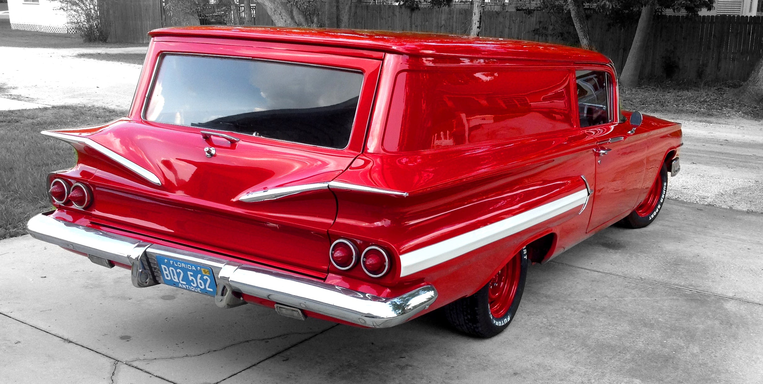
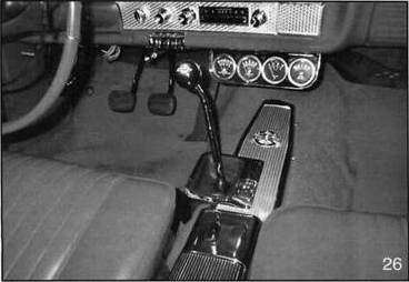
Photo #26 shows the finished product. Looks just like a factory 4- speed!! A shift knob is the last item to be installed and is the “icing on the cake.”
Notes about transmissions and bellhousings (and other useful info):
If you use a 1957-1963 Borg-Warner T-10, it will have a 10-spline input shaft, and a 16-spline output shaft, and use the same transmission slip-yoke as an early Powerglide or 3-speed. The later, Borg-Warner Super T-10 is 3/4-inch longer than the early T-10, and uses a 26-spline input shaft and 32- spline output shaft.
If you use a 1963-1970 Muncie M20 (wide ratio), or M21 (close ratio), it will have a 10-spline input shaft and 27-spline output shaft. The 1971 and later Muncie M20 and M21 are 3/4-inch longer than the early Muncie and have a 26-spline input shaft and a 32-spline output shaft.
Saginaw 4-speeds also use the 10-spline input shaft and 27-spline output shaft.
Make sure the transmission you choose has the speedometer housing on the left (driver’s) side. Muncie’s can be either side, depending on what type of car it came out of. (Some Chevelle’s had the speedometer housing on the right side.)
If you have a 3:08 to 3:55 rear axle ratio in your Impala, you would probably want to use a wide ratio 4-speed. For rear axle ratios of 3:70 to 4:56, you would probably prefer a close ratio 4-speed. All transmissions mentioned can be used without modifying or moving the crossmember on the Impala.
When converting an early Impala from a Powerglide or 3-speed to a 4- speed, the driveshaft will have to be shortened. The only exception is the 3- speed w/OD, which has the same length driveshaft as the 4-speed. If the later Borg-Warner T-10 or later Muncie is used, even an original Impala 4- speed driveshaft will need to be shortened the additional 3/4-inch.
The donor car I used (1963 BelAir 6cylinder with 3-speed) had a #3788421 bellhousing. This, I learned is a “63 only” bellhousing. On the “421” bellhousing, the hole for the transmission front bearing retainer is only 4 1/8-inches wide. Most transmissions (except ‘63) have a front bearing retainer that is 4 5/8-inches wide. Bottom line - if I really wanted to use this bellhousing, I would have to find a 1963 4-speed. I found a 1963 Muncie #3831704 wide ratio with the smaller front bearing retainer at a swap meet. Worked perfect with my bellhousing. Another option would have been to use a 1964 bellhousing (#3840383), which has the larger 4 5/8” hole, so any transmission would fit it.
On the subject of bellhousings, you also have to be careful how your starter bolts up. I had several 1962’s (small blocks) years ago in which the starter bolted to the bellhousing. On 1963 & 1964’s (small blocks), the starter bolts to the engine block, so a 1963 or 1964 bellhousing may not work on a 1962 or older small block. (Because there is nothing to bolt the starter to.)
That’s my story and I’m sticking to it!!! I don’t claim to be a transmission expert by any stretch of the imagination. These are just things I learned while researching and doing the swap. I welcome any comments or corrections.